1. Introduction
1.1 General Remarks
automar is a highly integrated graphical user interface for processing data collected on mar detectors (image plate scanner and CCD). The program covers all aspects of data reduction starting from the crystallographic pattern recorded on an image to the final intensities of observed reflections. In the course of this process, automar calls and executes programs that actually do the work. Thereby, automar acts as an editor of standardized input files for the relevant programs. When running the programs, automar collects the relevant information from the program output and reuses it. The goal is to reduce user's manual interaction to a minimum and to make operations safe and easily reproducible. Also, automar provides excellent graphical tools for analyzing images (display and editing of spot lists, verification of pattern prediction and integration box placement and sizes as well as visualization of results from indexing and scaling.
automar currently supports the mar data processing suite (programs marProcess, marPost and marScale), the MOSFLM suite of programs (ipmosflm and aimless) and the HKL suite (denzo and scalepack). From one interface, you can thus process data in 3 different ways with only one set of parameters. Data processing has never been more convenient! The coice of the program suite to use can be done on the fly with a single selection. The peak search and index step (programs marPeaks and marIndex is used as a common gateway to either suite since marIndex produces data integration parameters in a suitable way for either data processing suite.
Table 1 gives a summary of programs used by automar and their functions.
Table 1: Programs called by automar
| Program name | Description |
|---|---|
| marPeaks | Spot search using 2D diffraction images (mar345, marccd, etc.). |
| marIndex | Autoindexing of spots found by marPeaks |
| marPredict | Pattern prediction using parameters from marIndex |
| marStrategy | Data collection strategy optimisation using parameters from marIndex |
| marProcess | Data integration using parameters from marIndex |
| marPost | Summation of partials after integration with marProcess and postrefinement |
| sortmtz | Sorting of raw hkl as produced by ipmosflm |
| marScale, aimless, scalepack or xscale | Data merging, scaling and analysis |
| truncate | Conversion of intensities (I) to structure factors (F) |
| mtz2various | Conversion of "mtz" reflection-files into other formats |
| scalepackcvt | Format conversion utility for various formats |
| scalepack2mtz | Format conversion utility of CCP4-package |
| unique, cad, freerflag | CCP4-programs used for adding free R-factor column to mtz-files |
Each program can be run stand-alone. The Unix style man pages describe the usage of the individual programs. When working with automar, one usually doesn't have to struggle with nomenclature and proper selection of keywords. The program uses defaults where applicable and allows for modification of the parameters that really matter. In case one really needs to fine-tune, one can always add commands to the input files automatically produced by automar.
2.2 Coordinate System
The mar images are visualized as seen from the crystal, or along the beam, in an upright position. Its coordinates are interpreted as :
-
X : to the right
Y : up
as is usual for 2-dimensional systems. Note, however, that other programs (including marView and older versions of marpeaks) use other conventions when working with images in the mar180/mar300 formats.
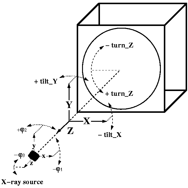
Detector tilt and rotation are defined by 3 rotation angles around X (tilt_X), Y (tilt_Y), and the detector normal Z (turn_Z, axis not used otherwise), in the mathematical +ve sense (see Figure 1). Positive tilt_X and tilt_Y bring the upper and left half of the detector closer to the sample, respectively. Positive turn_Z rotates the detector plane counter-clockwise as seen from the sample. To avoid confusion, crystal coordinates {x,y,z} are defined parallel to detector coordinates {X,Y,Z} making the z-axis anti-parallel to the beam direction.
Figure 1: Definition of the coordinate system

Crystal axes are defined by permutation of indices {l1,l2,l3} with values ±(1,2,3) where "1" denotes the a*-axis, "2" is the b*-axis and "3" is the c*-axis. "+" means parallel and "-" anti-parallel to a coordinate axis. In this way, l1 gives the reciprocal crystal axis along the x-axis and l2 the axis pointing "upwards" in the x-y-plane. The l3 index (towards the radiation source) is redundant, but may be explicetily set to yield a left- handed system.
Thanks to this definition, setting angles are always < 45 degrees, so you need not stand on your head and twist the fingers while imagining the orientation of your crystal. Setting angles are given in degrees and are numbered the same way but are applied from right to left:
-
PHI3 rotates around the z-axis (counter-clockwise when
looking along the beam). Applying this missetting first allows easy setting of
a crystallographic face diagonal along the rotation axis by
PHI3 = 45. + Delta-PHI3 where Delta-PHI3 is the true missetting angle. The 45 degrees are not altered by any of the other PHI1,2. - PHI2 rotates around the y-axis, again in the math. +ve sense.
-
PHI1 is a mere correction of the spindle axis
(if it is horizontal)
and may thus be used as an offset for the PHI axis reading.
Example: The hexagonal c*-axis runs along the PHI-axis (horizontal) and the a*-axis runs upwards ≥ (3,1,2). PHI1=30 brings the b*-axis exactly against the beam.
For primitive trigonal spacegroups marIndex suggests two alternative settings. At the indexing stage, there is no way to discern between them without comparing reflexion intensities from different crystals.
Note that MOSFLM describes the coordinate in a completely different way, that should be looked up in the MOSFLM User's Guide
2.3 Indexing Method
Like most auto-indexing programs, marIndex is based on difference vectors in reciprocal space although it has its own way of choosing a subset of spots and combining them to become reciprocal space vectors. From them it constructs and refines possible zone-axes which are well known in precession photography as real space vectors normal to reciprocal lattice planes ... not necessarily main cell axes.
The result of the vector analysis is the reduced primitive cell, and - on a purely geometrical basis - the most probable Bravais lattice, i.e. the highest symmetry that is acceptable within tolerance limits of refined zone-axes.
Zone-axes in the neighbourhood of the beam are used to sort spot coordinates into lunes, this way refining the beam centre. Intuitively, the centre is the intersection of all zero-layer lunes. The radius of convergence depends on how many zone-axes can be found and how close they are to the beam. In general it is more than a spot distance unless one long axis is so well aligned that its zero-layer lune vanishes within the beam-stop area, and all other low-indexed zones are far apart. In this case it is advisable to start with a different PHI setting.
marIndex repeats the zone-axis refinement and analysis with updated reciprocal vectors. At this stage, an orthorhombic Bravais lattice may be found where the initial vector analysis had suggested a monoclinic C-centred cell, etc.
The most reliable non-coplanar zones are now used to index all spots in the input list. Analysis of their reciprocal point coordinates w.r.t. the sphere of reflexion - both start and end position in case of rotation images - yields an approximate value for mosaicity/beam-divergence and updated setting angles. A full fit of calculated spot positions refines detector tilt and distance.
The final Bravais lattice analysis is based on all 25 equivalent "nearly Buerger-reduced" cells and the 44 possible transformations from primitive to Bravais lattices, implemented in the formalism of 6-dimensional "Gruber-space" (G6, based on the Niggli tensor components). The output list of derived Bravais lattices includes an error index which is the tangent between auto-indexed primitive cell G6-vector and its projection onto the 6-dimensional hyperplane or hyperline which describes the symmetry of the primitive cell underlying the particular Bravais lattice. The preferred choice at the end is based both on these error indices and the tolerances previously found for the primitive axes and angles.
For further reading, the following publications are suggested:
- A.J.M.Duisenberg (1991). J. Appl. Cryst. 25, 92-96
- W.Kabsch (1988). J. Appl. Cryst. 21, 67-71
- W.Kabsch (1993). J. Appl. Cryst. 26, 795-800.
- S.Kim (1989). J. Appl. Cryst. 22, 53-60.
- A.D.Mighell, A.Santoro & J.D.H.Donnay. "Old" Int.Tables I,5.1 (Kynoch Press)
- H.Burzlaff, H.Zimmermann & P.M.deWolff. "New" Int.Tables I,9 (Kluwer Ac.Publ.)
- I.Krivy & B.Gruber (1976). Acta.Cryst. A32,p. 297-298.
- W.Clegg (1981). Acta Cryst. A37, 913-915.
- L.C.Andrews & H.J.Bernstein, Acta Cryst. A44, 1009-1018.
- W.A.Paciorek & M.Bonin, J. Appl. Cryst. 25, 632-637.


